Table of Contents
Reverse Engineering a Cylinder
Solid Edge Tutorial
Introduction
The following tutorial has been created due to customer feedback regarding SHINING 3D’s all-in-one 3D scan to design solution. Using the EinScan Pro family of handheld multi-functional 3D scanners users should be able to capture complete and accurate data of their desired parts. The scan data can be meshed using the EinScan’s proprietary software and can then be imported directly into Solid Edge SHINING 3D Edition. This tutorial begins at this point and guides you on how to reverse engineer a cylinder in a user friendly, step by step guide. If you have any questions regarding any of our products please contact us direct to sales@shining3d.com for further assistance.
-
Getting started
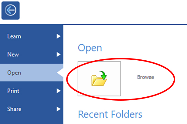
Open Solid Edge and click on browse icon.
-
Selecting the STL file
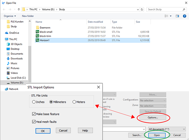
A new window will pop up once you begin to browse. Simply go to the location where you saved the STL and import the file.
To ensure you are using the right dimensions please mark the STL with the right mouse button. Then click on Option (circled red below) and check the dimensions. If everything is fine click on open (circled green below)
-
Choosing the template
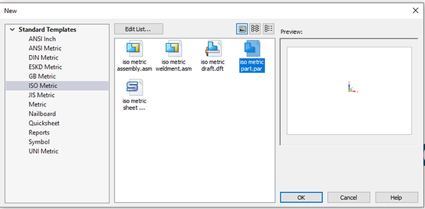
In this window you will have several options to choose from for the template. To reverse an STL file select the “iso metric part.par” option and press OK.
-
Successful import
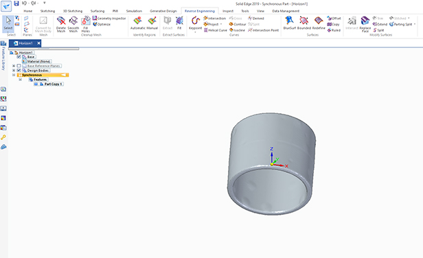
Once selected your screen should look the same as the image below. From there you should see a ribbon titled “reverse engineering”. If you do not see the STL directly please zoom in and inspect to see if it is further away from the coordinate system. If it is not visible, please try the import option again or write a mail to our support team (einscan_support@shining3d.com) for assistance.
-
Check the STL
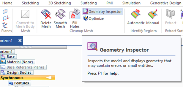
To ensure that the STL has no small holes or other errors use the “geometry inspection” function which is found at the top of the screen.
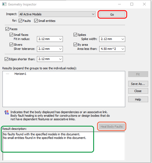
A new window will pop up. If everything looks the same as the image, click on the go button (circled red). At the bottom of the window you will see the result (circled green). If there are any issues found, please click and select the option “heal body faults” (surround red).
-
Mark regions
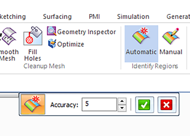
You can select the “Automatic” function to detect the regions or you can do it manually. In this case we will do it automatically.
If the function worked correct it should look like the image bellow.
-
Extract the surfaces
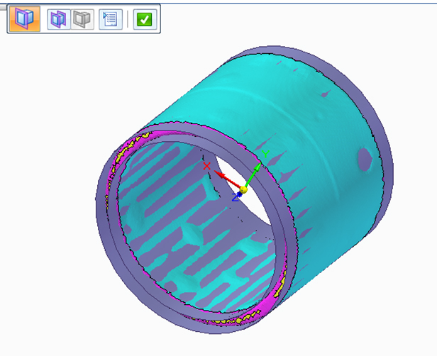
Here there are 2 ways to extract the surfaces. First is an automatic function that extracts only the selected areas. For the automatic option (circled red) the software extracts everything that it can find and sometimes it may be too much. See the image bellow.
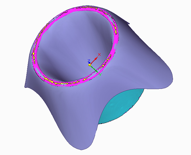
In this case we need to first select the inner and outside cylinder. To do that click on the outside cylinder with the left mouse button. To select the inside cylinder hold the CTRL key and then click on the inside cylinder with the left mouse button. Both should be green as pictured bellow. And now click this icon (circled red) to extract the selected regions.
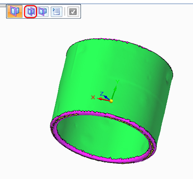
Here is the result of the extraction. Click on the green √ to accept the result. By pressing “ESC” on your keyboard you will end the function.
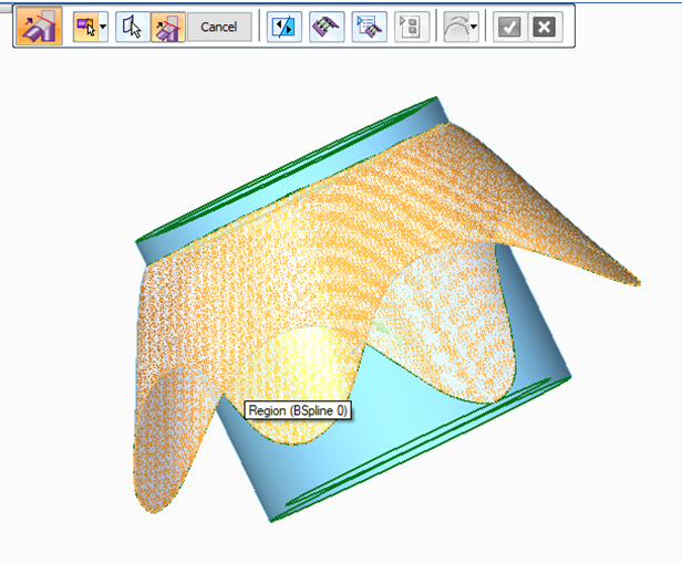
For the two ends of the pipe there will be shown two ways here. The first way is again to extract the. Follow the same steps as before. Click on the “extract” function -> click on the area at the end of the pipe and click extract. The software creates a B-Spline which should look like this.
-
Cutting function
The next step is to cut all away all surfaces which are not needed. For that use the use the intersect function (circled in red)
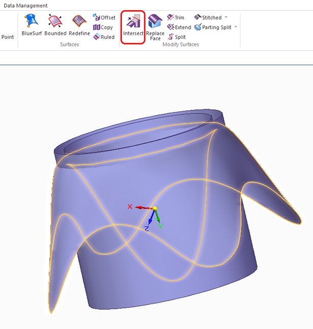
When activate, the function highlights all surfaces by clicking on it or holding the left mouse button and pulling a right angle over it. Click on the green √ to accept.
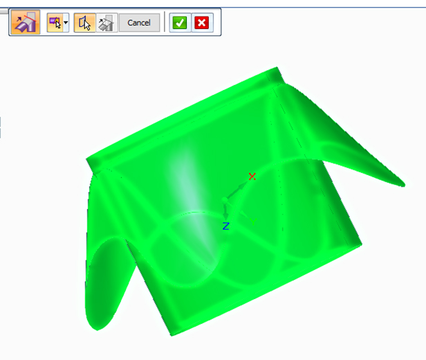
The colour of the surface should switch from green to light blue. As you can see in the picture.
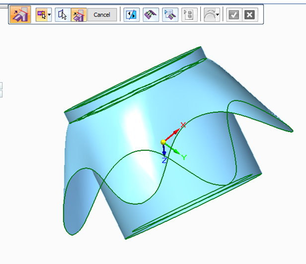
Now click on all surfaces that you want to delete. The surface that will be deleted will displayed in orange.
When all surfaces are cut, click on the green √ to accept it.
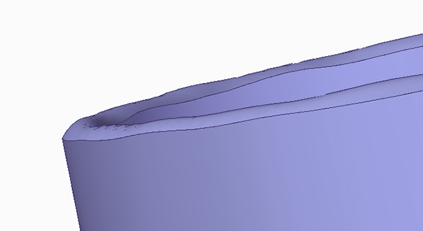
Now one end of the tube will look like the image below.
If you want to create a flat edge for the part, there is another way which is explained in the next step.
-
Create a flat plane
The first step is to hide all surfaces you’ve made so that only the STL is visible.
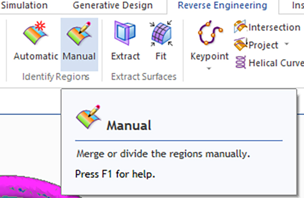
Now got to the “Manual” region function
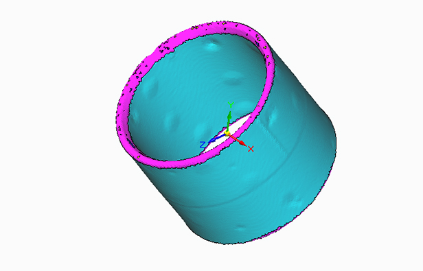
Select 3 or more areas where the plane should be. The new areas are circled in yellow.
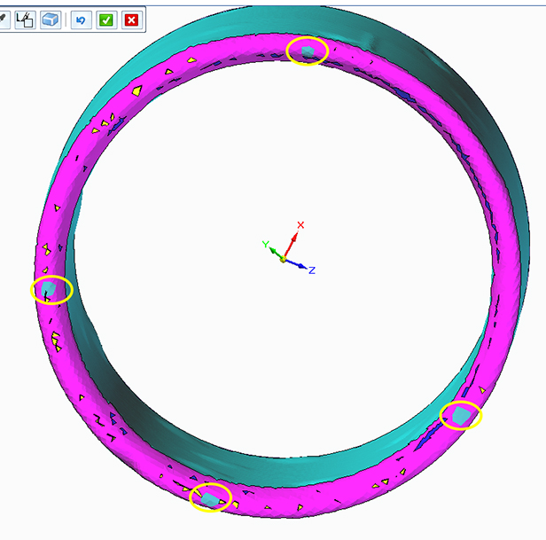
Press the √ to accept the new areas.
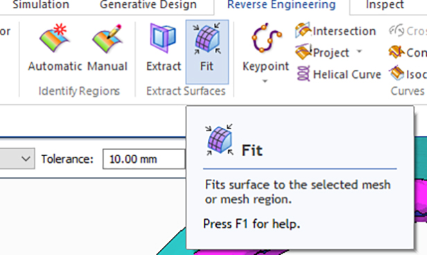
Now click on “Fit” function
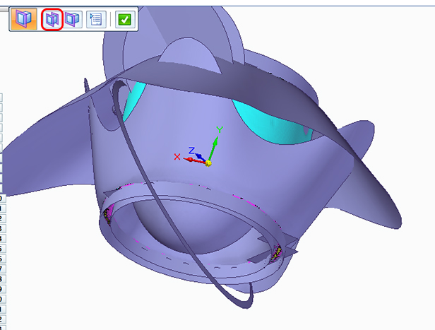
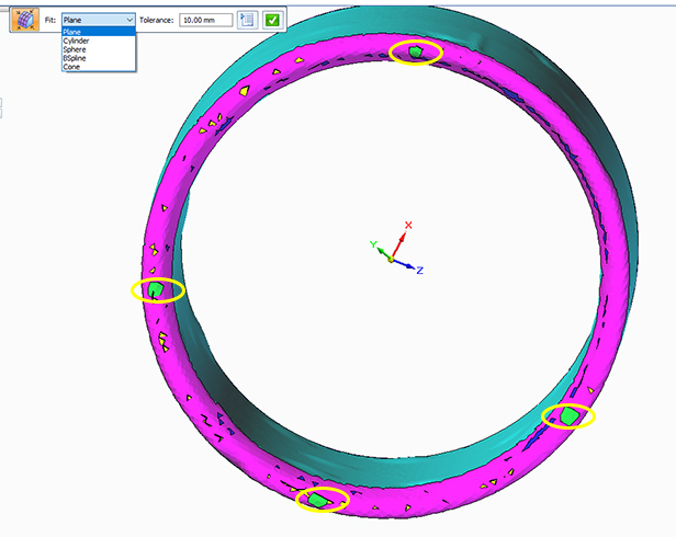
Now select “plane” in the drop down menu. Hold CTRL and click with the left mouse button on the areas you created previously (circled yellow). These areas should turn green. Click on the green √ to accept.
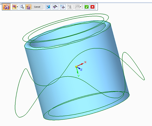
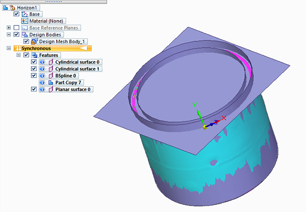
Now you have create a plane. The plane should intersect the cylinder like in the picture bellow. If not, use the extend function.
The next step is to cut the surfaces again. So go on the “intersect” function and select all surfaces, then click on the surfaces you don’t need.
-
Last step
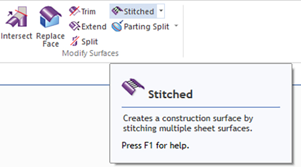
The last step now is to “stitch” everything together
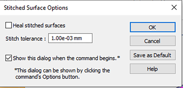
A new window will pop up. Click on OK to continue.
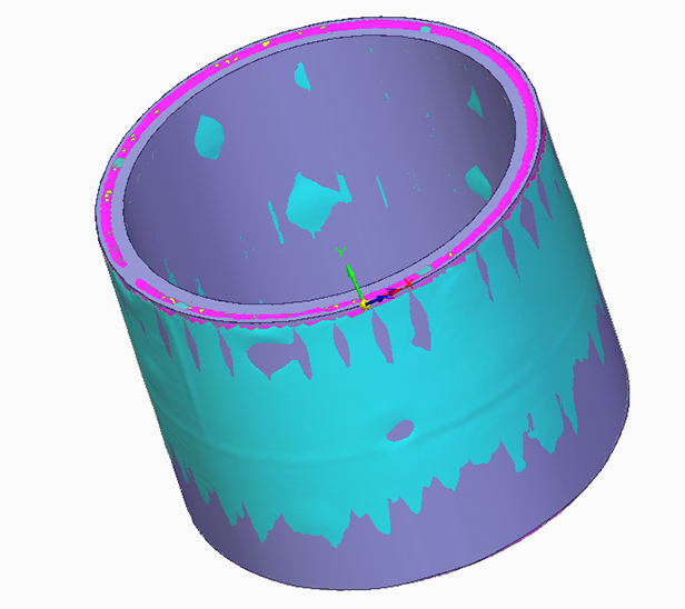
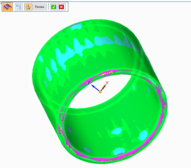
Select all surfaces that are green. You can do it manually by clicking on it or by holding the left mouse button and pulling a right angle over it. The surface should be green as in the picture below.
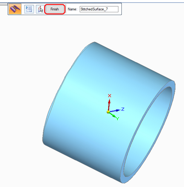
Click on the green √ to accept and now the part should be light blue. Click on “Finish” (circled red) to complete the function.
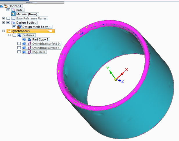
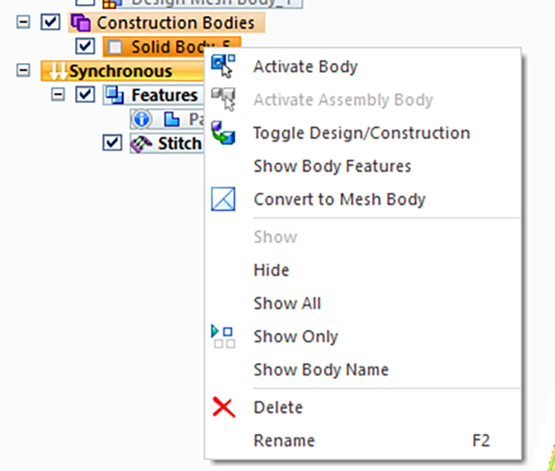
Once completed please click with the right mouse button on the Solid body. Click first on “active body” and then click the right mouse button to select “Toggle Design/Construction”
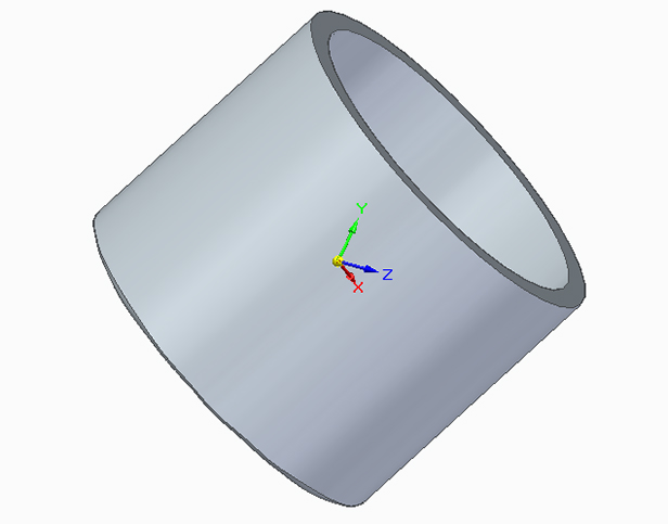
Your part should now be gray, as shown below.
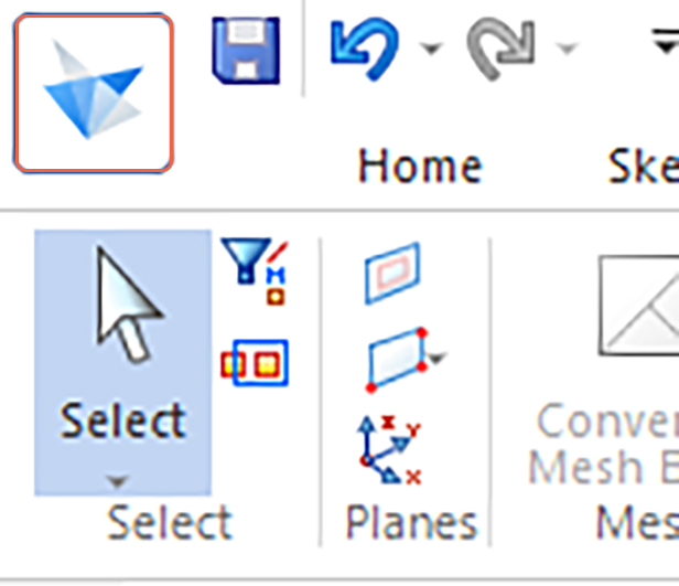
To save the part click on the SolidEdge icon (circled orange) in the left corner.
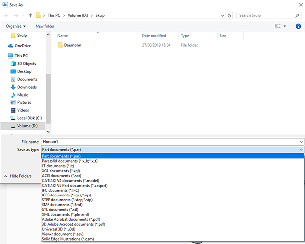
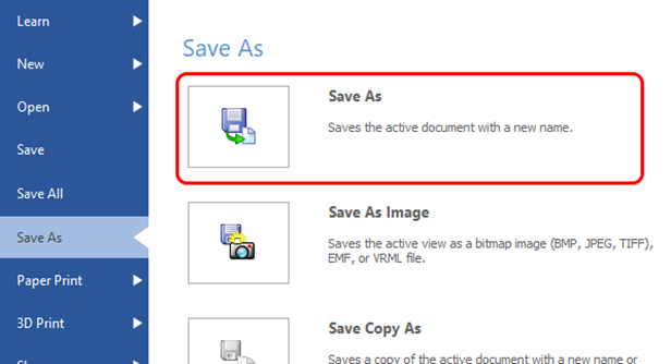
Slecect “Save as” (circled red)
Select either STEP or CAD in the drop down menu and then save the file.