Edward Van Zyl, a seasoned 3D scanning and printing expert from Manitoba, heads the company Dreamworks 3D Printing and Scanning. With extensive expertise in the realm of vintage car restoration and customization, he is enthusiastic about utilizing state-of-the-art equipment to capture intricate details of automotive components and then utilizing software to generate accurate 3D models. This article delves into the tips utilized by Edward for scanning with the EinScan HX Hybrid Light Source Handheld 3D Scanner and the reverse engineering of car parts through the use of Geomagic Essentials and Fusion 360.
Scanning And Printing An Arrow 50 Scooter Part
Edward chose the EinScan HX Hybrid Light Source Handheld 3D Scanner to finish the project.
In scanning process, Edward provides a small tip: utilizing miniature pyramids as markers rather than some of the ones that were attached to the object. This has the advantage of saving time and cost, as it eliminates the need for post-scan cleaning and the small pyramids can be reused. You may download files of pyramids here.
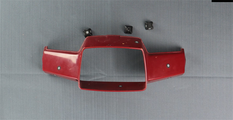
Arrow 50 scooter part and pyramids
In laser scan mode, EinScan HX has a maximum scan speed of 480,000points/s. It just took around 12 minutes to complete the whole scan of the component. And the laser scan mode of EinScan HX makes the scanned data accurate up to 0.04mm, you get a very accurate model for subsequent work.
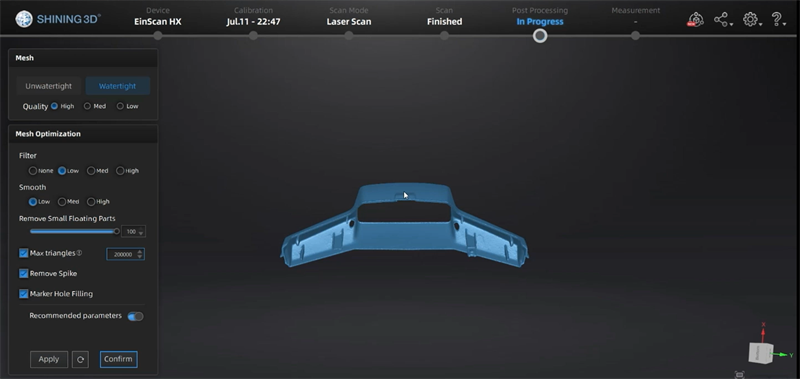
Scanned data of the Arrow 50 scooter part
Here we got the final result of the bambu carbon X1 printout.
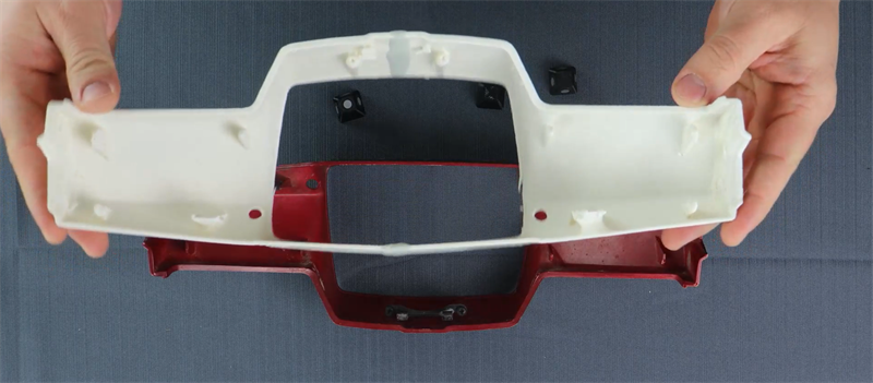
3D printed Arrow 50 scooter part
Cutting A Fender Using Geomagic Essentials
Edward’s goal was to cut a fender and make sure it was the right size for installation. Usually, he will print out the part for test, and in this case he offers an easy-to-print and material-saving trick.
He creates a small offset about 5 mm or even less, and cuts the part again, so that he gets a tiny piece of the fender, but maintains the geometry he need. 3D printing this thin piece was just as good for installation testing, and using only a minimal amount of printed material.
Cut the fender part to a suitable size
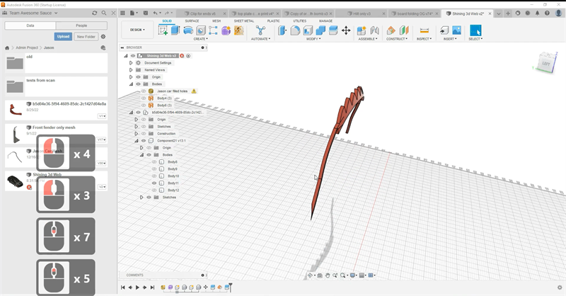
Tiny piece of the fender for test
Reverse Engineering An Engine Using Geomagic Essentials And Fusion 360
In this section, Edward shows the process of using Geomagic Essentials to extract features on the engine, and then using Fusion 360 to model the three holes in which he wants to simulate the mounting bolts.
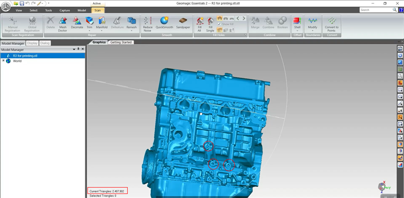
The engine needed to be reverse engineered
One thing to keep in mind here is that you need to maintain the mesh and the extracted features in uniform coordinates. This step ensures that the extracted features can be overlayed on the mesh in the right position. After extruding two cylinders of different sizes and modeling some threads, the mounting bolt is done.
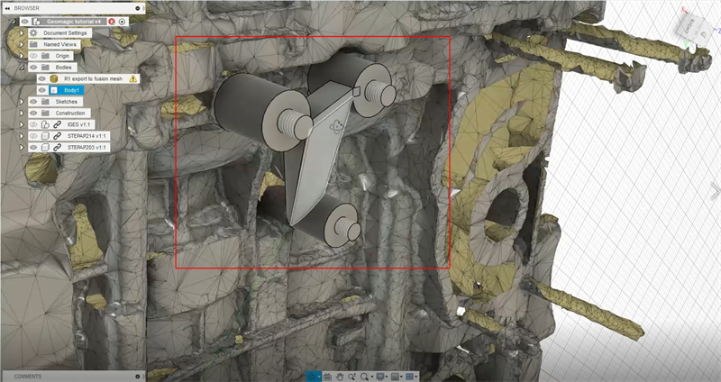
Modeled mounting bolts and bracket
This is basically how to go from scanning to printing of a part; how to use a mesh and model mounting bolts in Geomagic Essentials and Fusion 360. And it is clear how much can be done with a bundle of 3D scanners and softwares.
You may find more operation details in the playback video. If you found this content useful, please follow us so you won’t miss out on more information.


